
Build oneParts, part numbers, and the two that bite
What to buy to turn a NanoPi Zero2 into a Wi-Fi 7 capture sensor, with every part number written down so the build survives a dead listing. Two choices on this page are easy to get wrong in a way that looks right: the exact BE200 variant if you buy the Intel card, and which antenna connector you buy. Both have their own section.
Bill of materials
tap a row for detail
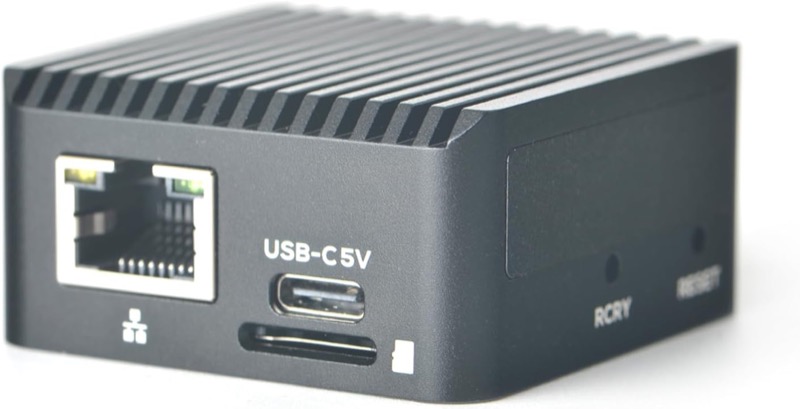 NanoPi Zero2
2 GB, no eMMC, with case · $49.99, free shipping
Required
Buy the 2 GB, no eMMC, with case option. Skip the bundled Wi-Fi card and SD card: the card that ships with it is neither the QCNCM865 nor the BE200, and you will supply your own SD.
- SoC
- Rockchip RK3528A, quad-core Cortex-A53
- Memory
- 2 GB LPDDR4X (1 GB variant also sold)
- Expansion
- M.2 Key E slot, PCIe
- Network
- Gigabit Ethernet, Realtek RTL8211F PHY
- Power / data
- USB-C
- Console
- UART header, 3.3 V, 1,500,000 baud
- Price
- $49.99, free shipping
- Source
- FriendlyElec · Amazon B0DHLC9SJ3
Amazon · FriendlyElec · Wiki
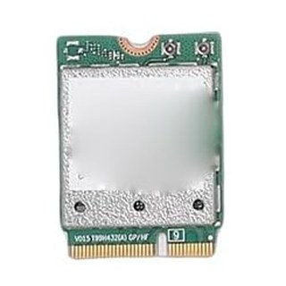 Qualcomm QCNCM865 (WCN7850)
Foxconn T99H432 · 320 MHz-capable · or the BE200 below
Pick one
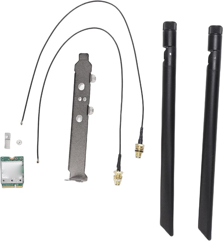
Our preferred radio, and the card we develop and test against. Identify it by the module rather than the listing: the board is silkscreened T99H432(A) beside the edge connector and enumerates as PCI 17cb:1107, subsystem 105b:e0f7. It is sold as a kit with two pigtails, two dipole antennas and a desktop bracket; the case build only needs the card. The BE200 below still works, and it is the card in this page’s photographs.
- Chip
- QCNCM865, Qualcomm FastConnect 7800 / WCN7850 hw2.0
- Module
- Foxconn T99H432
- PCI ID
- 17cb:1107, subsystem 105b:e0f7
- Form factor
- M.2 2230, Key E
- Radio
- Wi-Fi 7, 2×2, tri-band
- Max width
- 320 MHz on 6 GHz, measured on a Pi 5. On the NanoPi, 160 MHz is measured so far
- Driver
- ath12k, WCN7850 firmware with the ncm865 board file, both in the image
- 6 GHz
- Follows the sensor’s regulatory country. Intel cards learn their own; this one does not
- Price
- A little more than the BE200. Amazon shows the exact price only in the cart
- Source
- Cuifati kit · Amazon B0GXWM6VV9
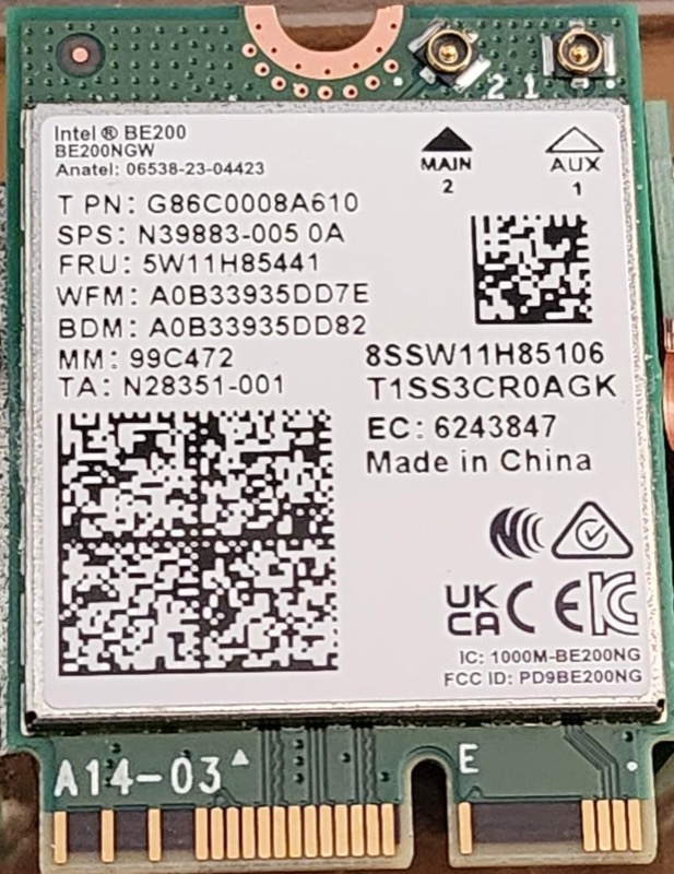 Intel BE200, non-vPro
Intel 282726 · must say “No vPro” · or the QCNCM865 above
Pick one
The part number matters. See Get the BE200 variant right before ordering — the label on the card itself reads BE200NGW either way, so a photo cannot tell you which variant is in the box.
- Intel part
- 282726
- Model
- BE200.NGWG.NV
- Variant
- Non-vPro, listed as “No vPro”
- Form factor
- M.2 2230, Key E
- Radio
- Wi-Fi 7, 2×2, tri-band, plus Bluetooth
- Max width
- 320 MHz on 6 GHz in monitor mode on the current image, tested on a WLAN Pi Go’s Gen2 PCIe link (the NanoPi’s link is also Gen2). The app offers up to 160 MHz today
- Driver
- iwlmld, firmware core 106
- Price
- $23.39
- Source
- Amazon B0DFKF4T56
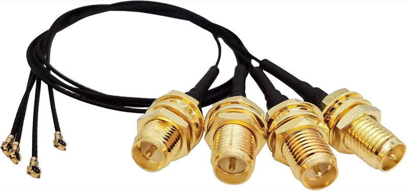 MHF4 to RP-SMA pigtails
15 cm, RP-SMA female, 4-pack
Required
Two needed, sold in fours. These carry the signal from the card’s tiny MHF4 sockets out to the case.
- Ends
- MHF4 (U.FL) to RP-SMA female
- Length
- 15 cm / 5.9 in
- Impedance
- 50 Ω
- Quantity
- 4 per pack
- Fits
- M.2 NGFF cards. Not Mini PCIe
- Price
- $9.99 for four
- Source
- Amazon B07S2LYC1F
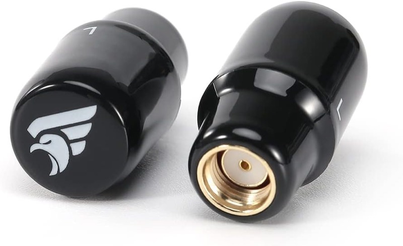 Osprey LHCP antennas
RP-SMA · the pocket-scanner pick · $19.88 for two
Required
Two, and this is the one we actually measured rather than guessed at. Across eight antennas swept on all three bands the Osprey was the most compact tested, and circular polarisation cost nothing on throughput — it even out-ran the larger Dixingtek on 5 GHz. Read the connector trap before ordering any alternative.
Know what you are trading. This is a 5.8 GHz FPV antenna, roughly 5.6–6.0 GHz, not a tri-band whip. It gives up some 2.4 GHz and it is not tuned for the top of 6 GHz. That is the price of something that genuinely pockets; if the sensor lives on a desk, the 5″ Oscium was the stronger all-rounder.
- Connector
- RP-SMA, mates with the pigtails above
- Polarisation
- LHCP, circular
- Band
- 5.6–6.0 GHz
- Gain
- 2.82 dBi
- Size
- Stubby, 14.1 mm diameter × 14 mm
- Quantity
- 2 per pack
- Price
- $19.88
- Source
- Amazon B0BM99SJCP
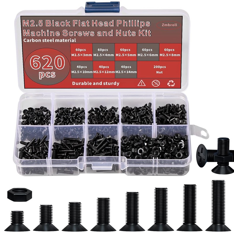 M2.5 screw assortment
M.2 retaining screw is M2.5 · $9.99
Required
The M.2 card is held down by a single small screw, and the M.2 standard specifies M2.5. An assortment is worth having because that screw is easy to lose and impossible to improvise.
The printed enclosure below eats two more lengths: M2.5 × 8 mm top-to-bottom at the antenna corners and M2.5 × 14 mm for the four centre holes. This kit has the 8 mm and not the 14 mm — its ladder runs 12, 16, 20 and skips straight over. Source the 14 mm separately if you are printing the enclosure.
- Thread
- M2.5, the M.2 retaining size
- Sizes
- M2.5 × 3/4/5/6/8/10/12/16/20 mm
- Head
- Flat head, Phillips
- Contents
- 620 pieces, flat head Phillips, with nuts and washers
- Price
- $9.99
- Source
- Amazon B0B3J58MMW
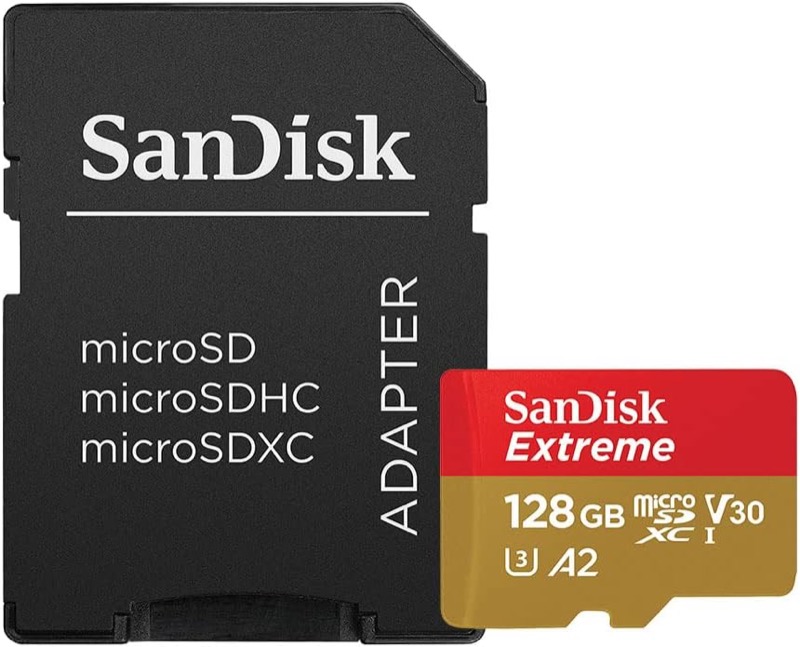 microSD card
A2 / V30 minimum · any size, it auto-expands
Required
Any size from 8 GB up. The image expands to fill the card on first boot, so buy for capture headroom, not for the image. Buy A2 and V30 for headroom, and see what a running sensor actually uses for the measurements.
- Minimum
- A2 and V30, so 30 MB/s sustained write
- Known good
- SanDisk Extreme microSDXC — C10, U3, V30, A2 B07FCMKK5X
- Price
- $12 for 32 GB up to $44.59 for the 128 GB Extreme
- Size
- 32–64 GB is a sensible middle
- Endurance
- “High endurance” is a nice-to-have, not required
- Before trusting it
- Benchmark the write speed. A card can read perfectly and write at a crawl
- Note
- The cheaper SanDisk Ultra line is A1/U1. The stock card in our build managed 12 MB/s regardless
Worth adding
nice to have
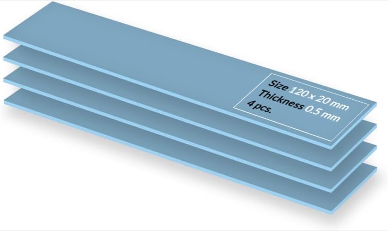 0.5 mm thermal pad
Case includes one; this is a better one
Upgrade
The case already ships with a pad, so this is not something the build needs to work — the stock one is just thin and cheap. Orb is firm that a pad is required: “the card needs the pad to transfer heat to the case and run reliably.” Replacing it with a decent 0.5 mm pad is a cheap upgrade. The sensor image also throttles the card’s transmit when it runs hot, but that costs rate, and the pad is what keeps you below the point where it engages. What the pad, a fan and the governor measured →
- Product
- ARCTIC TP-3
- Thickness
- 0.5 mm, matching the stock pad
- Sheet
- 120 × 20 mm, 4 per pack
- Do not go thicker
- Too thick stops the case closing flat and makes contact worse
- Price
- $7.49
- Source
- Amazon B09V518BXM
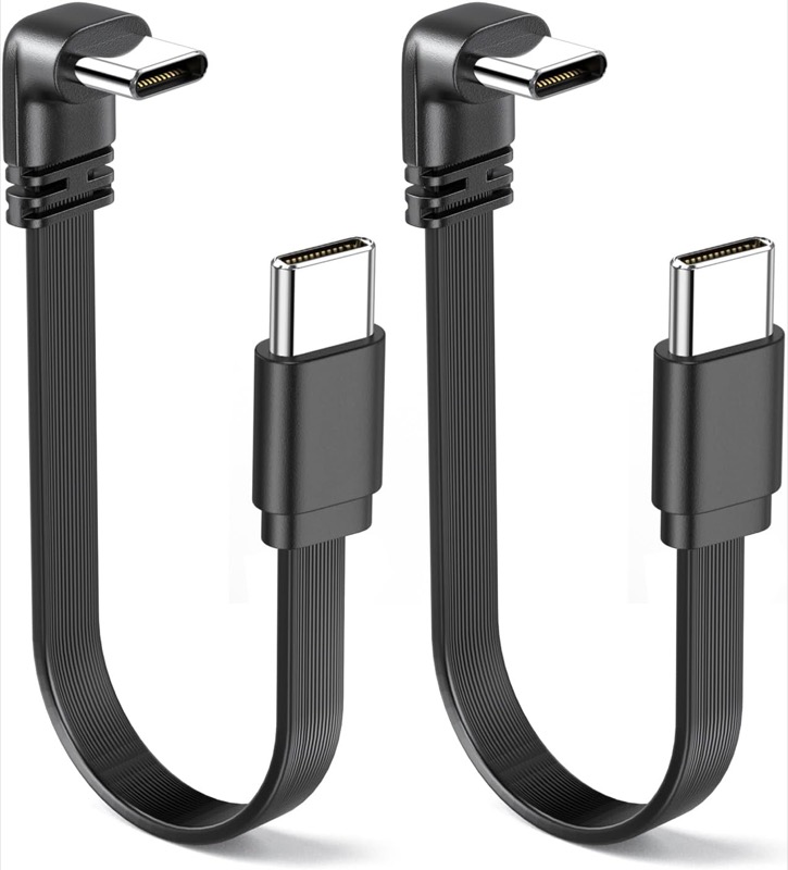 Short right-angle USB-C cable
10 cm, powers and networks in one
Optional
Powers the sensor and carries the network link at the same time. Plug it into a laptop or phone and the sensor appears at 198.18.42.1 with no ethernet involved. The right angle keeps it from levering on the port in a bag.
- Product
- JUXINICE 90° USB-C male to male
- Length
- 10 cm / 4 in, flat and pliable
- Quantity
- 2 per pack
- Price
- $9.99 for two
- Source
- Amazon B0CSW84W7J
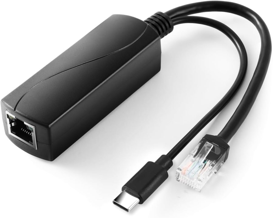 PoE splitter, USB-C output
One cable does power and network
Optional
For a sensor that lives where there is no outlet — a ceiling grid, a rack door, a riser cupboard. The splitter takes 48 V PoE in on one RJ45 and gives you data out on a second RJ45 plus 5 V at up to 4 A over USB-C, which is more than this board and either Wi-Fi card will ever draw. 802.3af alone budgets 12.95 W at the powered device, so an af switch port is enough; at is headroom.
It occupies the USB-C port. That port is how you get the NCM gadget link at 198.18.42.1 from a laptop, so a PoE-powered sensor is reached over ethernet or not at all — and since v1.0.7 there is no serial console on that port either. Budget for the UART header if the unit goes somewhere awkward. You also need a short RJ45 patch lead from the splitter to the board, which is not in the box.
The board's PHY is gigabit, so the 2.5G rating is headroom rather than a benefit. The USB-C splitter below is the way to keep the gadget link while this is powering the board. Used in our NanoPi testing without problems; the ratings below are the listing's.
- Product
- REVODATA 2.5G Type-C PoE splitter
- Model
- TYPEC0504G
- Standards
- IEEE 802.3af / 802.3at
- Output
- USB-C, 5 V / 4 A, 20 W
- Data
- 2.5 Gb/s passthrough
- Also needs
- A short RJ45 patch lead, splitter to board
- Price
- $15.29
- Source
- Amazon B0CHW5K5F4
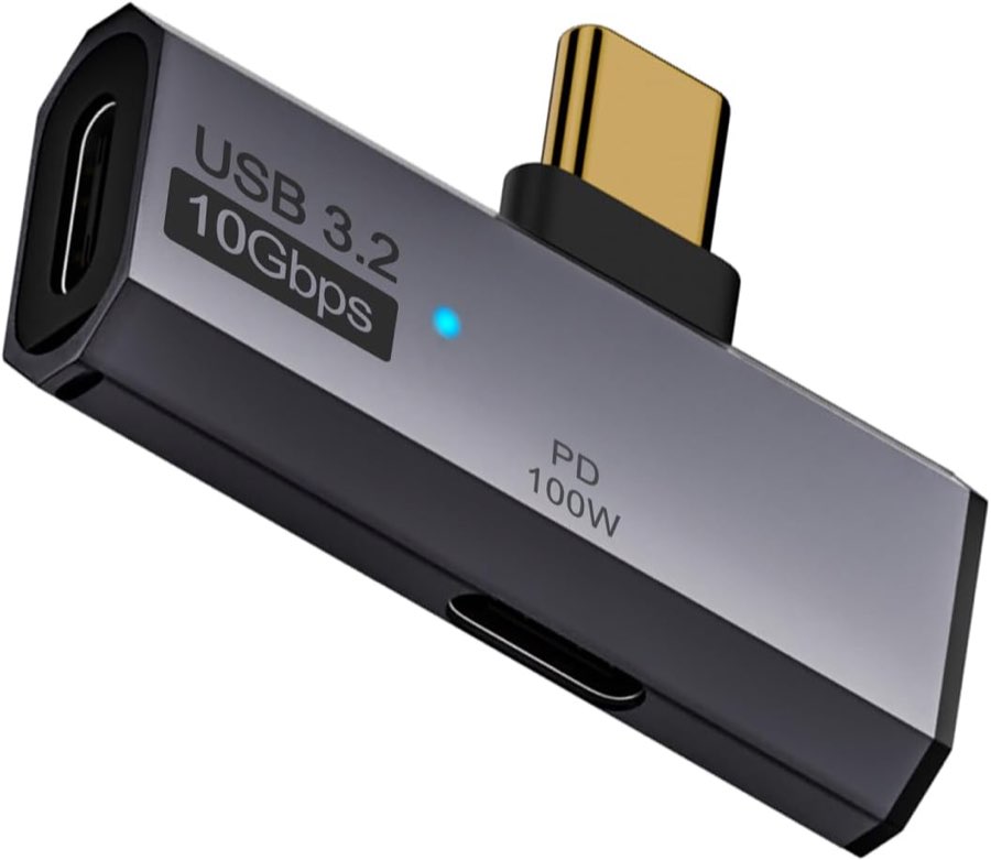 USB-C one-to-two adapter, 90°
Power and the gadget link on one port
Optional
The board has one USB-C port, and it is both how you power the sensor and how you reach it at 198.18.42.1 over the NCM gadget. Anything permanent in that port — a PoE splitter, a wall supply — takes the laptop link with it. This adapter is one male into two females, so the supply goes on one leg and the laptop on the other, and its right angle keeps the stack out of the printed enclosure's way.
One is in the field rig below, carrying power from a pocket battery. Used in our NanoPi testing without problems, alongside the PoE splitter above.
The PD100W and 10 Gbps ratings are irrelevant here in the same way the PoE splitter's 2.5G is: the board's port is USB 2.0 and the board wants 5 V.
- Product
- QIANRENON USB-C 1 male to 2 female, 90°
- Rated
- PD 100 W, 10 Gb/s — both headroom
- Use
- Supply on one leg, host on the other
- Price
- $12.99
- Source
- Amazon B0DDPRWVD5
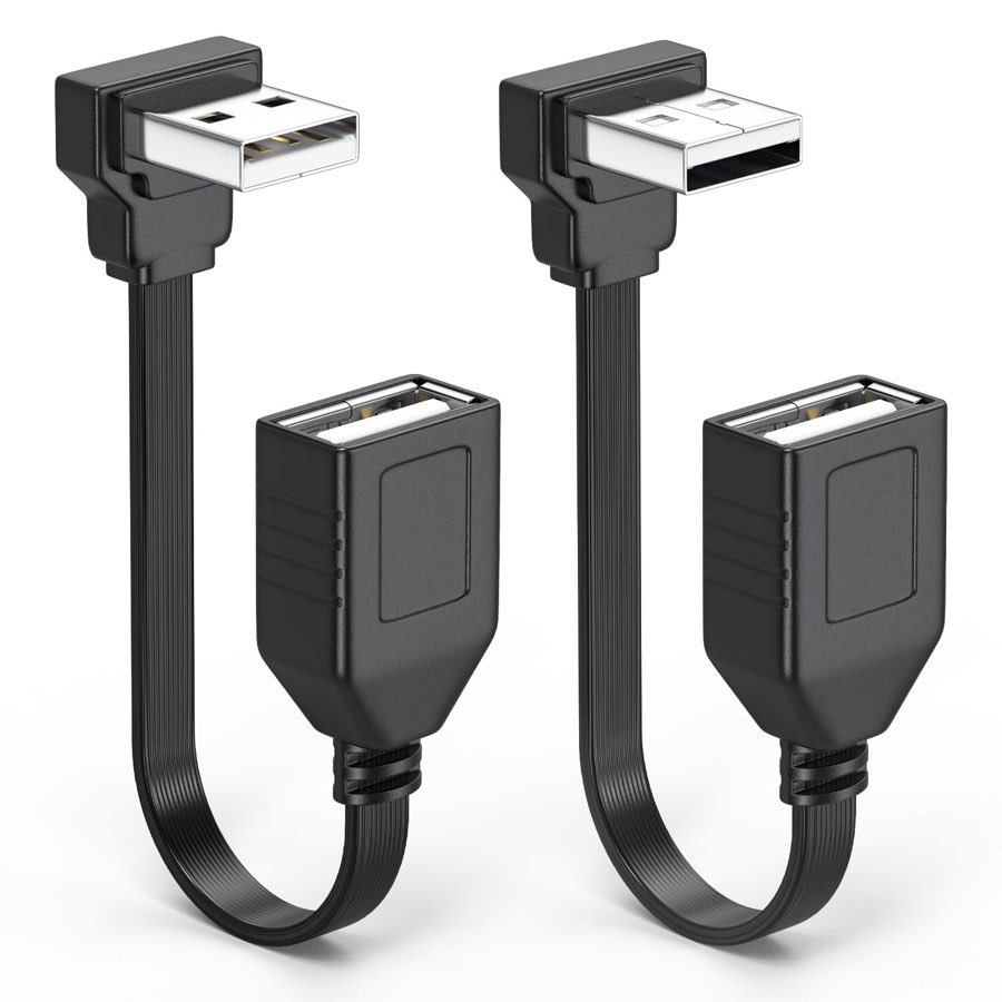 USB-A extension, 90°
Stops a USB radio levering on the port
Optional
The board has one USB 2.0 Type-A host port, and that is where a USB radio goes — an MT7921U, or the MT7925U inside a Netgear A9000. Those adapters are heavy and stick straight out, which is a lever on a through-hole connector every time the sensor is moved or bagged. A 10 cm right angle turns that into a cable pulling on a cable. The pack has one up-angle and one down-angle, so whichever way the port faces in your enclosure, one of them lies flat.
USB 2.0, which costs nothing here. The board's Type-A port is USB 2.0 whatever you plug into it, so a USB 3 radio is already running at USB 2.0 speeds and this cable takes nothing further away. It is the board that caps this, not the extension.
- Product
- JUXINICE 90° USB 2.0 male to female
- Length
- 10 cm / 4 in, flat and pliable
- Quantity
- 2 per pack — one up-angle, one down-angle
- Fits
- The board's single USB 2.0 Type-A host port
- Price
- $9.99 for two
- Source
- Amazon B0CDM7G5WH
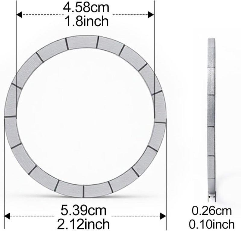 MagSafe magnet rings
53.9 mm outer · 2.6 mm thick · $7.99
Optional
For sticking the finished sensor to something steel, or to a 3D-printed mount. Sold for DIY and print-in projects rather than as a phone accessory.
The ring has a polarity and it is easy to fit backwards. A MagSafe array is a ring of alternating poles, so a ring seated the wrong way up repels the one in the phone case instead of latching. Offer it up to the case you actually intend to stick it to before committing it, and mark the face that held.
- Type
- Magnet ring, MagSafe-compatible
- Outer ø
- 53.9 mm / 2.12 in
- Inner ø
- 45.8 mm / 1.80 in
- Thickness
- 2.6 mm / 0.10 in
- Price
- $7.99
- Intended use
- DIY and 3D printing, accessory side
- Source
- Amazon B0GGNLD59P
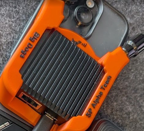 3D-printed MagSafe case
Free community design · MakerWorld
Optional
A community-published MagSafe enclosure for the NanoPi Zero 2 that you print yourself. This is the route to a sensor that sticks to a steel ceiling grid, a rack door or a tripod plate. Pair it with the magnet ring above.
It does not replace the stock case — it wraps it. The finned aluminium case goes inside the print, so the thermal pad and the metal it dumps into are still in the stack, and the external antennas still terminate on the board. Buy the board with its case, not on its own — the print needs it.
Printed and built here. See fitting the printed enclosure below for the parts of it that are not obvious: which screw lengths, which way the magnet ring goes, and where the pigtails run. Read the model page for print settings.
- Type
- Printable case, MagSafe
- Fits
- NanoPi Zero 2
- Price
- Free — you supply the filament
- Source
- MakerWorld model 3266641
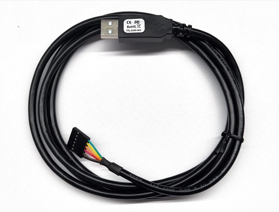 USB serial console cable
The only console, since v1.0.7
Optional
For watching the board boot, or recovering one that will not come up on the network. This is now the only console. v1.0.7 removed the CDC-ACM function from the USB gadget — it stopped some hosts enumerating the gadget at all — so a unit in a case has no console over USB-C any more. Do not buy a cheap CP2102 for this board — see the console runs at 1.5 Mbaud.
- Recommended
- FTDI TTL-232R-3V3
- Chip
- FT232R, 300 baud to 3 Mbaud
- Logic level
- 3.3 V signals
- Wire colours
- Documented by FTDI: black GND, orange TX, yellow RX, red +5 V
- Connect
- GND, TX, RX only. Leave red disconnected
- Price
- $17.99
- Source
- Amazon B00DDF8TV6
Buy the FTDI-branded part. Listings exist that put the string TTL-232R-3V3 in the title under someone else's brand for about the same money, and the chip inside is what decides whether 1.5 Mbaud works. The ASIN above is FTDI's own.
What it costs
prices checked 2026-09-04
Two builds, depending on whether the antennas live inside the case or screw onto the outside. Everything above the antennas is identical.
| Part | Price | Internal | External |
|---|---|---|---|
| NanoPi Zero2, 2 GB, case | $49.99 | • | • |
| Qualcomm QCNCM865 kit, or | a bit more | • | • |
| Intel BE200, non-vPro | $23.39 | • | • |
| microSD | $12–$44.59 | • | • |
| M2.5 screw kit | $9.99 | • | • |
| Thermal pad, optional upgrade | $7.49 | • | • |
| MHF4 to RP-SMA pigtails | $9.99 | • | |
| Osprey LHCP antennas | $19.88 | • |
Internal antennas: roughly $95 to $135. The spread is almost entirely the SD card — a 32 GB A2 card at the bottom, the 128 GB SanDisk Extreme at the top — plus the optional thermal pad. Both totals are priced with the BE200. The Qualcomm kit costs a little more, and Amazon shows its exact price only in the cart.
External antennas: roughly $125 to $165. The same build plus pigtails and a pair of Osprey antennas, which together add about $30.
Prices exclude tax and were read from the listings on 4 September 2026. They move; the part numbers do not, which is why those are what this page is really for.
The internal build assumes the antennas mount inside the case rather than on external connectors. If you are fitting adhesive MHF4 flex antennas instead of the pigtail-and-Osprey pair, budget for those separately — they are not listed above.
Get the BE200 variant right
the expensive typo
The BE200 ships in vPro and non-vPro variants that look identical, mount identically and differ by a few characters in the part number. You want the non-vPro card.
Intel 282726 · BE200.NGWG.NV · "No vPro"
Listing title reads: Intel 282726 Nt Be200.ngwg.nv Intel Wi-fi 7 Be200 2230 2x2 Be+bt No Vpro Retail
Check the listing title for the letters .NV and the words No Vpro before you pay. A seller photo of the card will not tell you which one is in the box.
The connector trap
pin meets socket, always
SMA and RP-SMA use the same thread. A mismatched pair screws together perfectly, feels solid, and never makes electrical contact. There is no mechanical tell.
We have already paid for this. In an antenna comparison on 2026-08-27, three of four antenna sets were RP-SMA on an SMA jack. Every one threaded on. All three datasets were stray coupling through an open connector and had to be thrown away. A seating check passed, because an open connector still hears plenty at close range; the giveaway only appeared across frequency, as a 13 dB hole at 6295 MHz beside near-parity at 5975 MHz.
One more habit worth keeping from that run: if two physically different antennas measure identically, treat it as a connection fault until proven otherwise. Two disconnected antennas both read −64.0 dBm.
What a running sensor actually uses
measured 2026-09-04
Rather than guess at the RAM and storage a capture sensor needs, we measured one during capture.
| Measured on a live sensor | Value | What it means |
|---|---|---|
| Total RAM | 1.92 GiB | The 2 GB board |
| Idle | 253 MB | Full system, Orb running |
| Peak during capture | 281 MB | Only 28 MB above idle |
| tcpdump itself | 7 MB | It streams, it does not buffer |
| Swap used | 0 | Never came close |
| Card write, mid-range | 12.1 MB/s | Flat from 16 MiB to 256 MiB, no falloff |
| Card write, Samsung 128 GB | 21.7 MB/s | Also flat; about 1.75× the other |
| Card read, both | 67–70 MB/s | Identical — this is the board’s ceiling, not the card |
| Capture to card vs to RAM | 0% loss both | Storage was not a limit at the rate tested |
1 GB of RAM would be enough. Peak usage during capture was 281 MB, and tcpdump streams to disk rather than buffering in memory. We still suggest the 2 GB board because the price gap is small, but do not buy it expecting capture to need it.
A mid-range card is fine. Two cards measured on this board sustain 12 and 22 MB/s, against the roughly 0.8 MB/s a busy 2.4 GHz capture was actually writing. Buying A2 and V30 buys headroom and a guarantee, not a fix for a problem you are likely to have.
Ignore read speed when judging a card here. Both cards read at 67–70 MB/s despite writing at very different rates, because read is capped by the RK3528’s SD host controller. A benchmark that leads with read numbers will tell you nothing about this board.
One 180-second capture on a busy channel lost 51% of its frames — 160,621 dropped against 152,625 written — at roughly 1,700 packets per second. It is not the card. The same card re-tested at 12 MB/s with no errors, and capturing to RAM instead of to the card made no difference at all.
The cause is still unidentified. Ambient traffic has since dropped to about 150 packets per second, where nothing drops in any configuration, so it is not currently reproducible. If you see heavy loss on a busy channel, the card is not the first place to look.
Benchmarking a new card before trusting it is still worth the thirty seconds, because a card that reads normally can still write slowly, and a capture gives no sign when it is losing frames.
# On the sensor. The image checks this itself once per boot and
# publishes the result, but you can ask any time:
sudo wc-storage-check
#   GOOD: SD card writes at 21.7 MB/s.

# Or measure it by hand:
sudo dd if=/dev/zero of=/var/tmp/w.bin bs=1M count=64 conv=fdatasync
sudo rm /var/tmp/w.bin
Size is free to choose: the image ships a 2.1 GB root partition and expands to fill the card on first boot. Ours grew to a 13.9 GB partition on a 14.6 GB card with no intervention.
Assembly
about 20 minutes · photographed on a real build
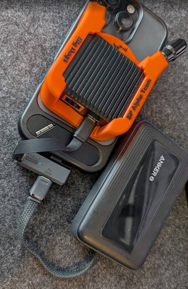
What you are building: the sensor magnet-mounted on the back of a phone, the finned aluminium case visible inside the print, an antenna on the corner, and power arriving from a pocket battery through the short right-angle USB-C lead and a one-to-two adapter marked USB 3.2 10 Gb/s PD 100 W. Nothing in this picture is bolted to anything.
Open the case
Already-installed Wi-Fi card: some NanoPi versions arrive with a Wi-Fi card already installed. To replace that card, disconnect its antenna connectors before removing its retaining screw.
Take the stock antennas out by the cover, not the antenna
Push the corner of the antenna cover to release it. Pushing on the antenna itself is how you damage one: it is a thin flexible element on a fragile lead, and it is not what the retention is holding. The slots it frees are where the pigtails go.
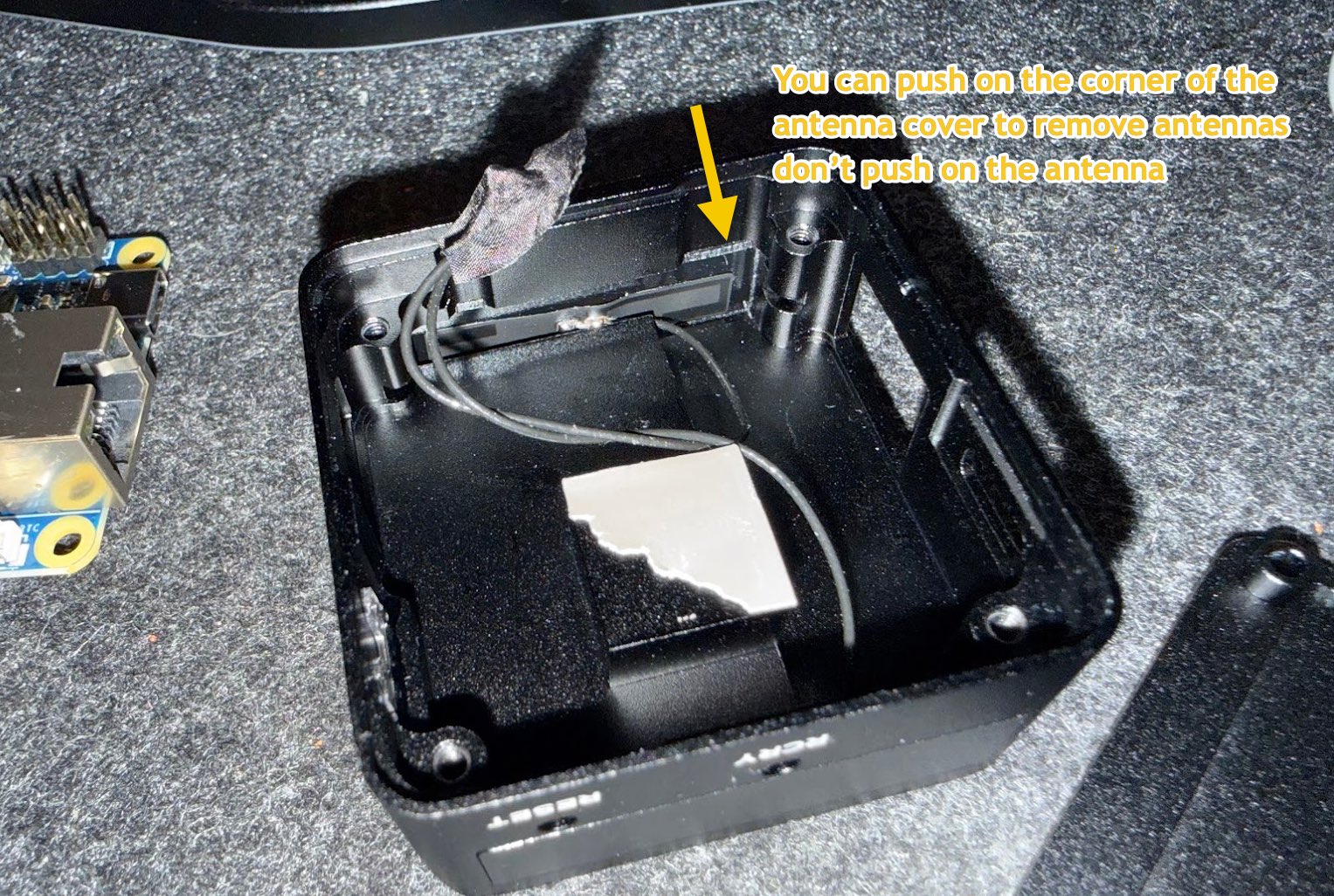
Click for the full-size photograph.
Mount the RP-SMA ends and fit the antennas
Mount the RP-SMA ends in the case with their washers and nuts. Start by hand. A correctly sized tool may be used very gently to snug the SMA mounting nuts. Hold the connector steady so the coax does not twist, and do not overtighten.
Check one last time that the pigtail shows a pin and the antenna shows a hole. Screw the antennas on finger tight. Leave the card ends disconnected until the case is positioned and the leads are routed.
Into the SMA / antenna case
The rest is the printed enclosure, and it does not replace the aluminium case — the case slides into it. Fit the thermal pad after connecting both antenna leads, before closing the lid. If you are keeping the stock internal antennas, skip steps 2–6, seat the Wi-Fi card and reconnect both antenna leads in step 7, then fit the thermal pad in step 8, close the aluminium case and continue at step 11. The following seven steps show the printed-enclosure build in assembly order.
The cable relief is how the case goes in
The notch moulded into the print is not only clearance for the coax — it is the entry the case slides in past. Line the case up on that side rather than trying to drop it in square.
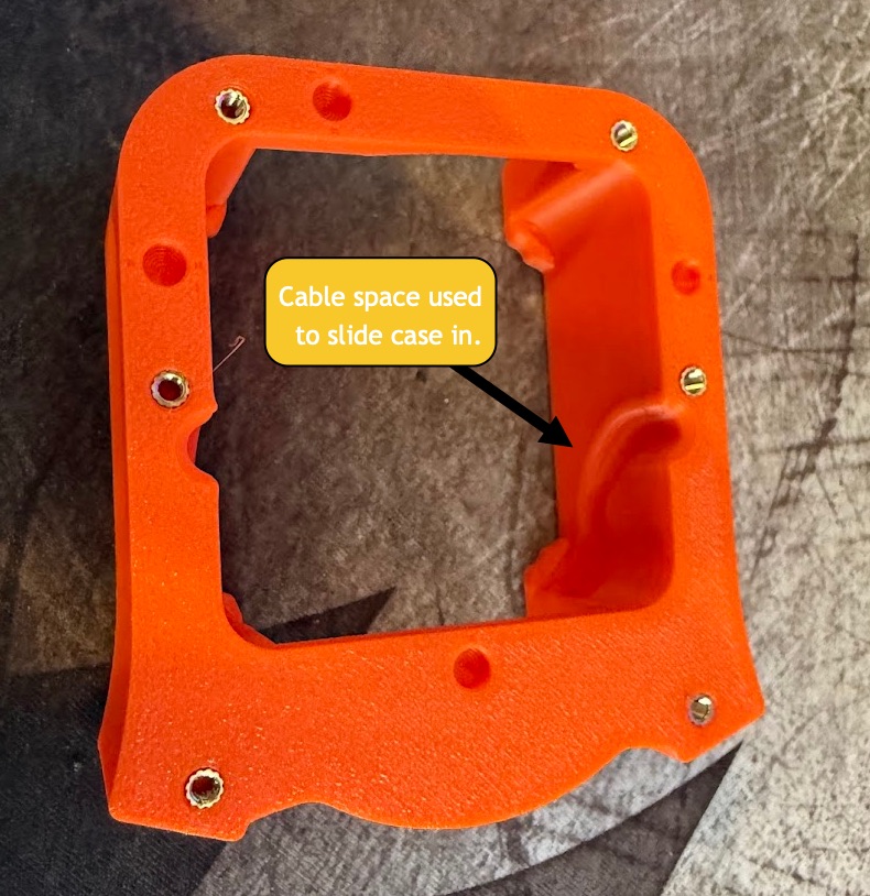
Click for the full-size photograph.
Run the leads out through the case passthroughs
The aluminium case has passthroughs that let the coax out beside the boards, so nothing is pinched between case halves. Slack is not a problem — there is a void above the board that stores the excess neatly, and coiled slack in there is better than a taut lead pulling on an MHF4 connector.
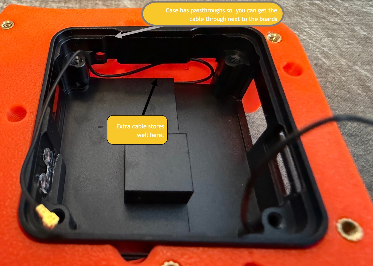
Click for the full-size photograph.
Push the SMA boot in as the case slides
The rubber boot on the SMA lead catches on the enclosure lip on the way in. Press it in with a fingernail while the case slides rather than forcing the case — the thing that gives if you force it is the connector, not the print.
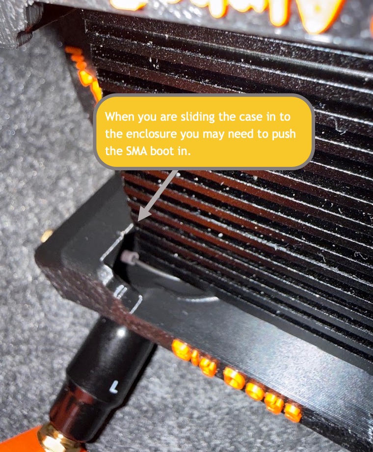
Click for the full-size photograph.
Seat the Wi-Fi card and clip the pigtails onto it
The QCNCM865 or BE200 goes into the M.2 Key E slot at an angle, then presses flat under its retaining screw. If it will not sit flat, it is not fully home in the slot.
Now that the SMA ends are mounted, the case is positioned and the leads are routed, connect both pigtails to the card. MHF4 connectors seat with a small, definite click. They are fragile and meant to be pressed straight down, not rocked. Both cards mark their two MHF4 sockets: on the BE200, MAIN is 2 and AUX is 1, marked with triangles beside each socket. Populate both. With a matched pair of antennas, which lead goes on which socket does not matter.
What a clean cable install looks like: both leads on the card, dressed flat across the module, nothing standing proud and nothing taut. This is what you are aiming at before the lid goes back on.
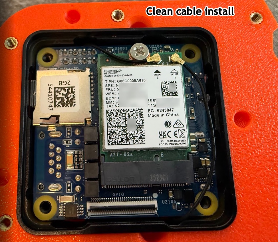
Click for the full-size photograph.
Fit the thermal pad
With both antenna leads connected and dressed flat, fit the thermal pad. The case comes with one. Use it, or swap in a better 0.5 mm pad. Cut a piece to cover the card's shield can and lay it on top. It bridges the gap to the case, which is the only heatsink this card gets. Do not substitute a thicker pad to "be safe": too thick stops the case closing flat and makes contact worse.
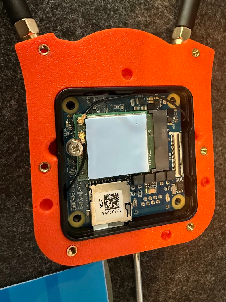
Thermal pad placed directly on the BE200's shield can.
Click for the full-size photograph.
Fit the magnet ring, and check which way up
The ring seats from the inside, so it goes in before anything is screwed together. A MagSafe array is a ring of alternating poles, so a ring fitted upside down pushes the phone case away instead of latching. Offer it up to the case you actually intend to stick it to, find the face that holds, and mark it — the two faces are identical to look at.
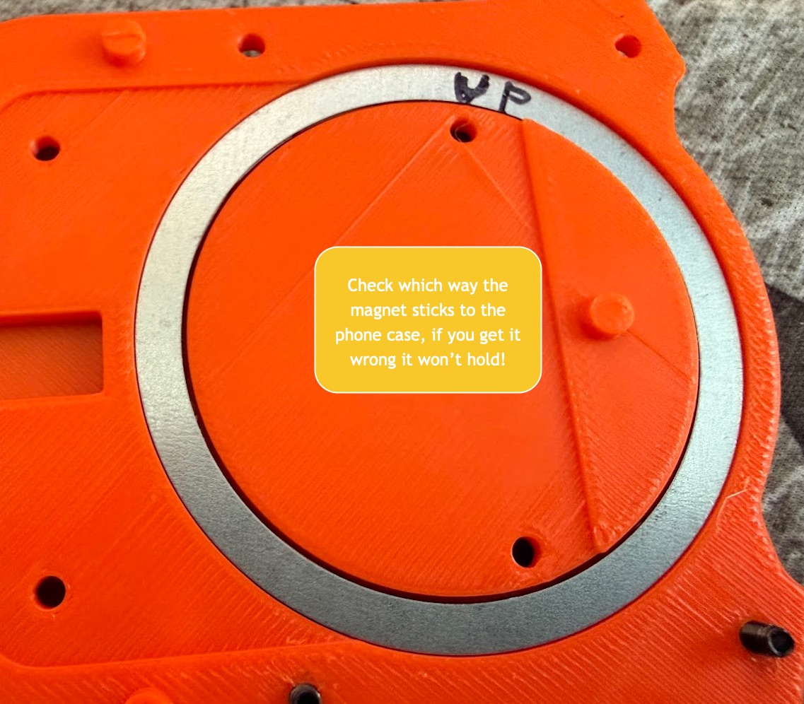
Click for the full-size photograph.
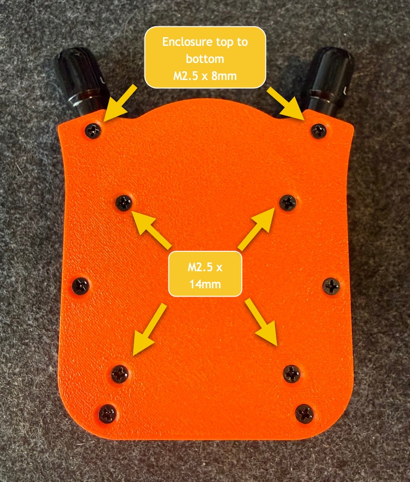
Two screw lengths, and the kit only has one of them
M2.5 × 8 mm runs the enclosure top to bottom at the two antenna corners. M2.5 × 14 mm takes the four centre holes. The 620-piece assortment listed above covers the 8 mm and not the 14 mm — its ladder goes 12, 16, 20 — so buy those separately or you will get to the last step and stop.
Click for the full-size photograph.
Flash the card and boot
Write the unified factory image, insert the card, and allow several minutes on first boot: it expands its storage and may reboot once on its own. The installation guide has the full first-boot steps.
xz -dc wlan-commander-sensor-2.1.36-factory.img.xz \
  | sudo dd of=/dev/sdX bs=4M status=progress conv=fsync
Confirm the radio came up
Claim the sensor with its one-time setup code over ethernet, or straight down the USB-C cable at https://198.18.42.1/, then ssh wlanpi@198.18.42.1 with the password you chose. A healthy BE200 reports three bands and no disabled channels.
iw reg get | head -2
iw phy phy0 info | grep -c 'MHz \['     # expect 110
sudo dmesg | grep -i 'loaded firmware'  # expect core 106
With the QCNCM865, check that ath12k found the card and that the regulatory country is set. In the world domain, 00, it has no 6 GHz at all.
lspci -nn | grep 17cb:1107
sudo dmesg | grep -i ath12k            # WCN7850 hw2.0, no errors
iw reg get | head -2                    # your country, not 00
The console runs at 1.5 Mbaud
why the cheap adapter fails
This board's debug UART runs at 1,500,000 baud at 3.3 V. That single number rules out most of the cheap adapters, and it does so silently: you get a connection and a screen of garbage, which reads like a dead board rather than a wrong cable.
| Chip | Maximum rate | Handles 1.5 Mbaud? |
|---|---|---|
| FT232R | 3 Mbaud | Yes |
| CP2102C | 3 Mbaud | Yes |
| CP2104 | 2 Mbaud | Yes |
| CP2102, the common cheap one | 1 Mbaud | No |
Connect ground, TX and RX only. Leave the red +5 V lead disconnected: the board is already powered over USB-C, and feeding it a second supply through the header is how you back-power a running board.
Buy an adapter with individual leads rather than a moulded 4-pin block. Separate leads let you leave the power wire off, and they make a swapped pair a five-second fix instead of a rewire. FTDI documents its colours, which is the other half of the problem: black is ground, orange is TX out of the adapter, yellow is RX into it.
# macOS, once the adapter is plugged in
ls /dev/cu.usbserial-*
screen /dev/cu.usbserial-XXXX 1500000
About the photographs
hosted here, not hotlinked
The product photographs are the sellers’ and are served from this site rather than linked to Amazon, so the page keeps working when a listing is pulled. The specifications beside them are facts, recorded in full for the same reason: a dead link should cost you a search, not the build.
The assembly photographs are ours, taken and annotated on the build described here.
Original research and documentation by WLAN Geeks. Sources and credits · Report a documentation issue